I want to bend the legs of resistors and capacitors neatly.
Issue solved
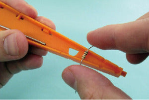
With the Lead Bender, lead wires can be bent at right angles with a single touch.
The "Lead Bender (RB-5)" is a simple bender for lead components. It is a very useful item when using components neatly on breadboards and universal boards.
Features of the Lead Bender
Lead wires of axial components such as resistors and diodes can be bent at right angles with a single touch.

TO-92 type transistor leads can also be bent to 2.54mm pitch.

Forming process is also available so that it can be mounted floating from the board.

How to use video
Usage 1: Bending lead wires
Lateral bending
-
Set the part on the slot of the width you want to bend.

-
Bend the lead wires of the component with your fingers.
-
When the bent part is at a right angle, you're done!

Vertical Bending
-
Use a projection (width = 2.54 mm) for longitudinal bending process.

-
Fix the lead wire of the component so that it is pressed against the projection at the position where you want to bend it.

-
Bend the lead wires along the protrusions with your fingers.

-
Bend the lead wires until they are parallel, and you're done!

Completed!
Folding is completed. It can now be completely inserted into a universal board (2.54mm pitch).

Usage 2: Lead wire forming process
Use the forming process area when you want to mount components floating from the board.
Forming process Outward
-
Set the pre-folded parts in the misots with matching widths.
- The image shows a 10 mm wide part.

-
Insert the "forming process rod" into the hole and push the lead wire of the part toward the side where the hole is wider.
- (In the image, the leads are pushed outward.

-
When both sides are processed, the part is complete!


Forming process Inward
-
Set the pre-folded parts in the misalignment whose widths match.
- The image shows a 15 mm wide part.

-
Insert the "forming process rod" into the hole and push the lead wire of the part toward the side where the hole is wider.
- (In the image, the leads are pushed inward.

-
When both sides are processed, the part is complete!


Completed
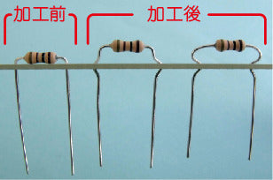
Formed resistor mounted on a universal board.
- Note that the pitch is one step larger or smaller depending on the direction of the resistor.

Usage 3: Bending TO-92 type transistor
The legs (leads) of a 3-terminal transistor can be spread evenly at a certain height.
-
Set the transistor.

-
Spread the leads slightly with your fingers.

-
Bend the lead wires at both ends along the hole with the "Forming Stick".

-
Finished!

-
The formed transistor mounted on the universal board.
