How to use UB-LED01 LED stick substrate (5-serial parallel connection type)
Table of Contents
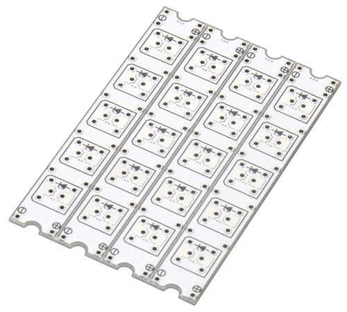
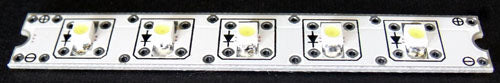
Products
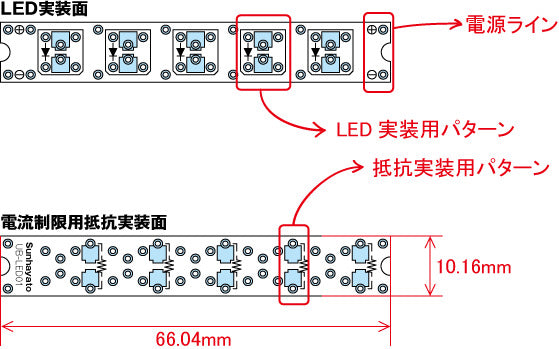
- Surface (LED mounting surface)
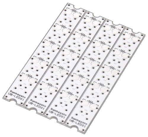
- Back side (resistor/constant-current diode mounting surface)
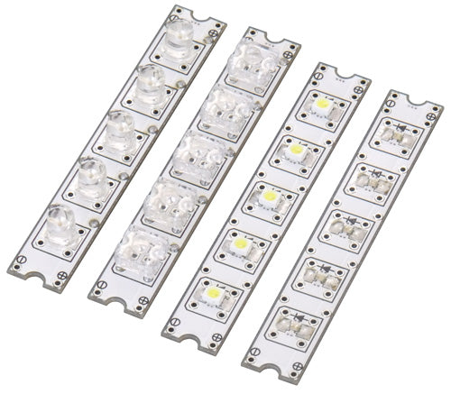
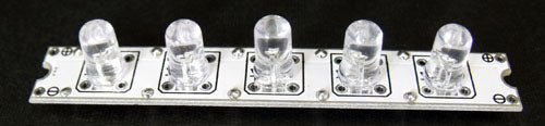
- LED mounting example
Features of LED Substrate
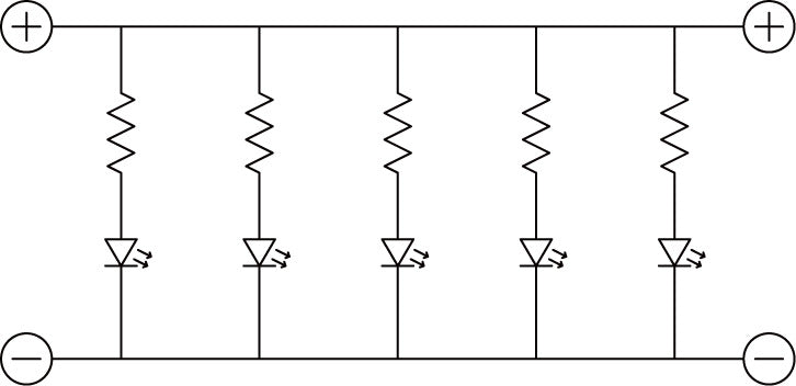
- Parallel connection of 5 LEDs on the board
- Small stick shape
- Divided into 4 pieces by V-cut
Example of use
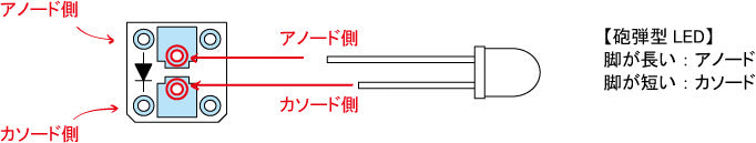
- Bullet-type LED (3, 5, 10 mm dia., etc.)
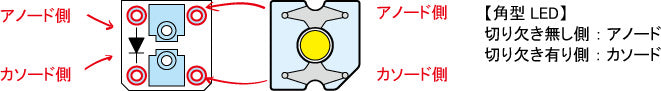
- Rectangular LED (Flux type)

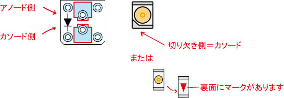
- Surface mount LEDs (1608 to 3528 size)
Resistors are like this when mounted on the back side.
(Lead type resistors can be mounted on the front side as long as they do not hit the LEDs.)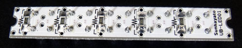
Size and circuit diagram
- Outline drawing

- Circuit diagram
The following explains how to use LEDs in parallel connection using UB-LED01.
First, let's look at the "current-limiting resistor.
The higher the current flowing through an LED, the brighter the LED. However, if a current exceeding the LED's rating is applied, the LED will break or its life will be shortened.
The resistor that adjusts the amount of current flowing to the LED is called a "current-limiting resistor.
This time, the calculations were made with "power supply voltage = 5 V," "current (IF) to LED = 10 mA," and "forward voltage (VF) = 1.8 V" for the LED used.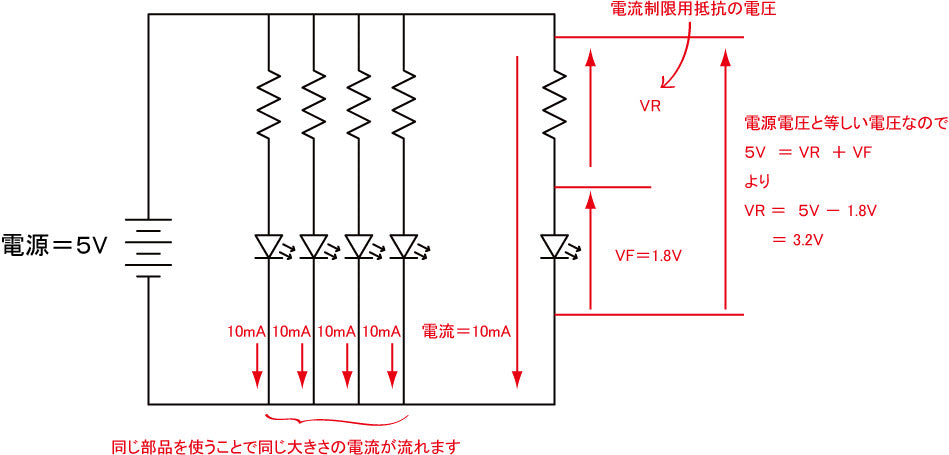
The voltage applied to the current-limiting resistor is calculated as VR = 3.2V from "power supply voltage (5V) = VR + VF.
Also, since the current flowing is determined to be 10mA, it is 320Ω from Ohm's law "V = R × I".
The actual resistor value used may not be exactly the same, so 330Ω, which is the closest to 320Ω in the E24 series, is used.To calculate the current-limiting resistance, the "Current Limiting Resistance (for LED lighting)" in Transistor Technology is useful.
Electronics Formulas Online Calculation Sheet | Transistor Technology
http://toragi.cqpub.co.jp/tabid/316/Default.aspx